Chapter 1: System Components
Architecture, component responsibilities, interfaces, and engineering boundaries of the Environmental Noise Monitoring System
1.1 System Architecture
The ENMS is structured around a modular, layered architecture that separates field-level acoustic capture from platform-level analytics and integration. The core system boundary encompasses the noise monitoring station and the central platform, connected via secure transport with synchronized time references. Optional components — including meteorological sensors, edge gateways, event snapshot cameras, and multi-microphone acoustic arrays — extend capabilities without altering the core data model.
The station enclosure houses all field-side electronics: the Class 1 microphone and weatherproof windscreen, the preamplifier, the SLM/DSP compute module, local data storage, communications hardware, power supply and conditioning, surge protection, and the enclosure itself with thermal management. The platform side handles data ingestion, time-series storage, object storage for event packages, rule-based QA/QC, alerting, reporting, GIS services, device management, and identity/audit functions. Supporting infrastructure — UPS, distribution panels, lightning grounding, network switching, and server room environments — is treated as a dependency layer outside the core boundary but essential for reliable operation.
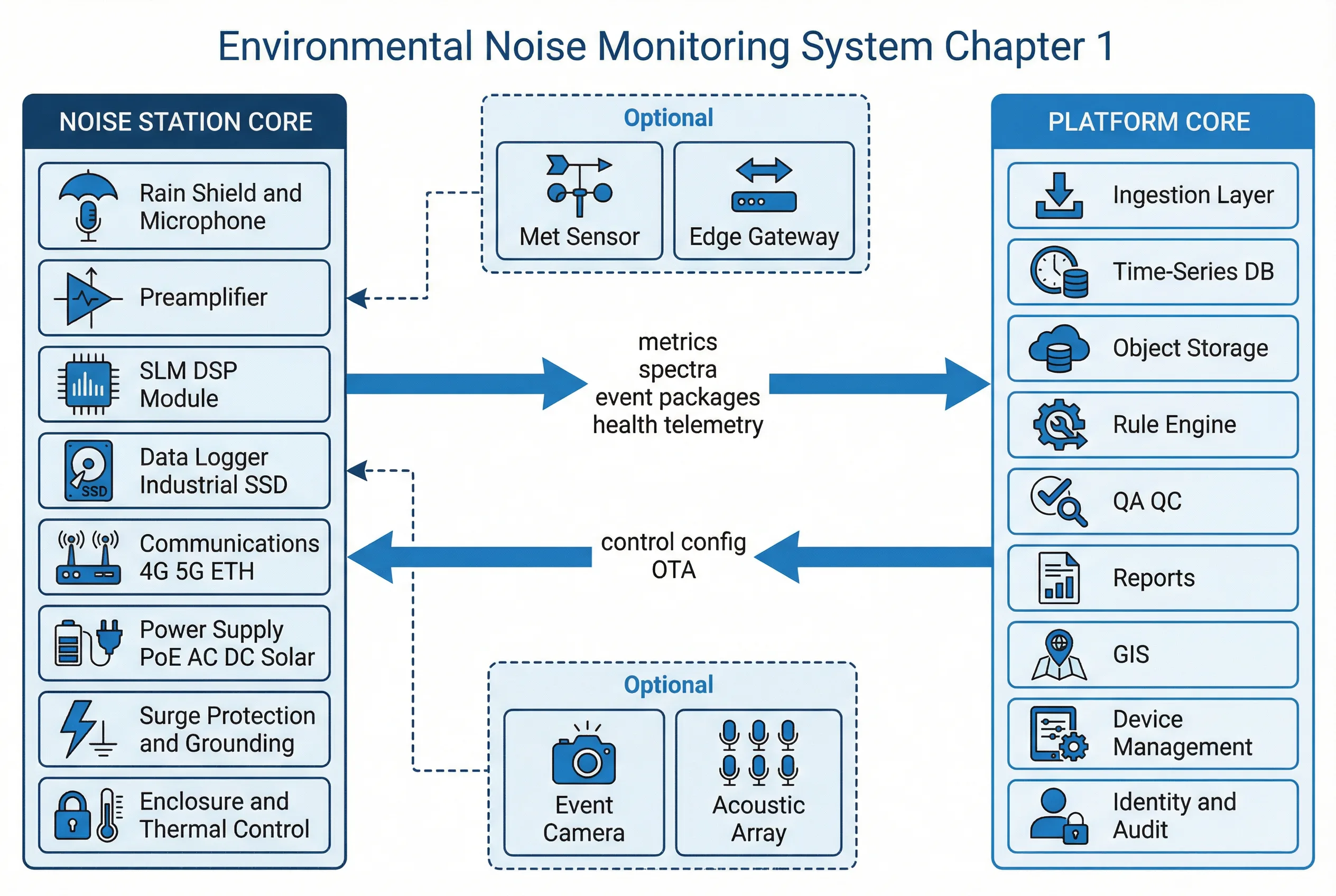
Figure 1.1: ENMS System Architecture — Core Boundaries, Optional Components, and Data/Control Flows
Core vs. Optional Boundaries
Core: Station + Platform + Secure Transport + Time Sync. Optional: Meteorological sensor, Edge gateway, Event snapshot camera (privacy-controlled), Multi-mic acoustic array. Supporting: UPS, distribution, lightning grounding, network, cabinet/room infrastructure.
Layered Responsibilities
- Field Layer: Accurate acoustic capture; environmental hardening; local buffering (≥7 days); first-pass QA (clipping/overload detection); secure time synchronization; basic self-check and fault reporting.
- Edge Layer (Optional): Site aggregation for multi-station clusters; protocol bridging (Modbus/RS485 → IP); offline resilience with local MQTT broker; local maintenance portal for technician access.
- Platform Layer: Data ingestion and validation; QA/QC rule engine; time-series analytics; alerting and escalation; reporting and evidence generation; device fleet management and OTA; audit trail and access control.
- Integration Layer: Regulatory reporting via REST/SFTP; data sharing with GIS systems; ticketing and work order integration; external data ingestion (traffic, flight schedules, construction permits).
Key Data and Control Flows
The data flow follows a pipeline from 1-second sampling at the microphone through 1-minute aggregate computation, metadata tagging, local commit to buffer storage, transmission to the platform, validation, QA/QC flagging, time-series storage, and downstream analytics, alerting, and reporting. The control flow operates in the reverse direction: policy and threshold authoring on the platform propagates versioned configurations to stations via staged rollout, with acknowledgement and audit logging at each step. Calibration records, firmware packages, and time synchronization policies all traverse this control path.
1.2 Component List & Responsibilities
Each component in the ENMS has defined inputs, outputs, and key performance indicators (KPIs). Mismatches between component specifications and deployment requirements are a leading cause of data quality failures, legal challenges, and repeated maintenance visits. The diagram below provides an engineering-level overview of all ten primary components and their inter-relationships.
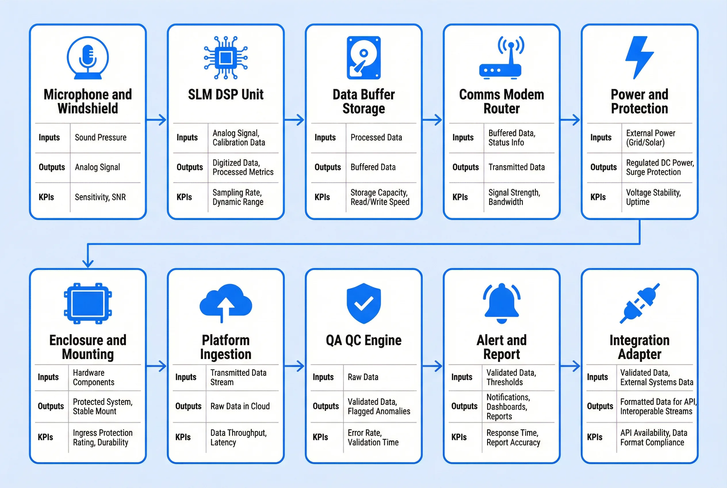
Figure 1.2: ENMS Component Overview — Inputs, Outputs, and KPIs for Each Major Component
| Component | Inputs | Outputs | Key KPIs | Mismatch Risk |
|---|---|---|---|---|
| Class 1 Microphone & Windscreen | Acoustic pressure | Analog/digital signal | Sensitivity stability (dB), self-noise floor, moisture resistance | Wrong class → non-compliant evidence; poor windscreen → wind-induced bias |
| SLM / DSP Compute Module | Mic signal, calibration data | SPL metrics, spectral bands, overload flags | IEC class compliance, dynamic range, processing latency | Class 2 used for enforcement → legal challenge; insufficient dynamic range → clipping |
| Data Buffer Storage | Processed metrics and event packages | Buffered data for retransmission | Endurance (TBW), capacity (days), read/write speed | Consumer-grade SD → wear-out and data loss; insufficient capacity → gaps |
| Comms Modem / Router | Buffered data, status telemetry | Transmitted data to platform | RSRP/SINR, uptime, reconnect time | Single SIM with weak coverage → chronic gaps; no VPN → security exposure |
| Power & Protection | Grid/PoE/solar input | Regulated DC power, surge-protected supply | Voltage stability, surge rating, thermal margin | Undersized PSU → resets; missing SPD → lightning damage |
| Enclosure & Mounting | All internal hardware | Protected, thermally managed system | IP rating (≥IP65), IK rating, thermal range | IP54 in wet zone → water ingress; no sunshield → overheating |
| Platform Ingestion | MQTT/HTTPS/SFTP payloads | Validated, deduplicated records in time-series DB | Ingestion latency, dedup rate, schema validation pass rate | No schema versioning → integration breaks on firmware update |
| QA/QC Engine | Raw metrics, met data (optional), calibration records | Flagged data, quality labels, calibration reminders | Flag precision/recall, false alarm rate, rule coverage | Poorly tuned rules → false exceedances or missed events |
| Alert / Report Module | QA/QC output, threshold rules | Notifications, dashboards, compliance reports, evidence packages | Alert latency, report generation time, export correctness | Missing audit trail → evidence rejected in enforcement |
| Integration Adapter | Platform data, signed exports | Formatted payloads to regulatory/GIS/ticketing systems | API availability, export success rate, schema compliance | Proprietary closed interface → vendor lock-in and high TCO |
1.3 Supporting Infrastructure Dependencies
While not part of the core ENMS boundary, supporting infrastructure directly determines system reliability and data integrity. Power quality affects station uptime and data completeness. Lightning protection and grounding determine hardware survival rates in exposed outdoor environments. Network infrastructure determines latency, redundancy, and security posture. Time synchronization infrastructure (GNSS receivers or authenticated NTP servers) determines the evidentiary validity of all timestamps. Each supporting dependency should be assessed during site survey and documented in the project BOM and acceptance test plan.
| Infrastructure Element | Requirement | Failure Impact | Acceptance Check |
|---|---|---|---|
| Power supply (grid) | Stable AC within device input range; dedicated circuit recommended | Station offline, data gaps, potential hardware damage | Voltage measurement, breaker labeling, load test |
| Lightning protection & grounding | Type 2 SPD at site entry; device-level SPD; ground resistance per site class | Repeated hardware failures, safety hazard | Grounding resistance test record, bonding inspection |
| Network / cellular | RSRP ≥ −105 dBm; VPN endpoint; VLAN isolation | Data gaps, security exposure | RSRP/SINR baseline, VPN stability test |
| Time synchronization | GNSS preferred; NTP with authentication; drift alarm ≤ 5 s | Wrong timestamps → wrong compliance windows → legal challenge | Drift audit report, NTP reachability check |
| Solar + battery (remote sites) | Sized for worst-case autonomy (≥3 days); battery health monitoring | Station offline during cloudy periods | Autonomy calculation, battery state-of-health check |