Chapter 11: Installation & Debugging
Site survey requirements, installation procedures, commissioning steps, and debugging protocols for environmental noise monitoring systems
Proper installation is the foundation of accurate and reliable noise monitoring. Errors made during installation — incorrect microphone height, inadequate vibration isolation, improper cable routing, or insufficient weather protection — can introduce systematic measurement errors that persist for the entire operational life of the station. This chapter provides comprehensive guidance on pre-installation site survey requirements, step-by-step installation procedures, commissioning protocols, and debugging techniques for resolving common installation issues.
11.1 Installation Requirements — Site Survey
A thorough pre-installation site survey is mandatory for every monitoring station. The site survey determines the optimal microphone position, identifies potential interference sources, assesses power and communication availability, and documents the baseline acoustic environment before the monitoring station is installed.

Figure 11.1: Professional pre-installation site survey showing acoustic engineers conducting baseline measurements, GPS coordinate recording, and distance measurements at an urban monitoring location prior to station installation
The site survey team should include at least one qualified acoustician and one installation technician. The survey should be conducted under representative meteorological conditions (wind speed <5 m/s, no precipitation) and should include measurements during the dominant noise periods for the intended monitoring purpose. The survey report becomes part of the project documentation and provides the baseline against which post-installation measurements are compared.
| Survey Item | Method | Requirement | Documentation |
|---|---|---|---|
| GPS coordinates | GNSS receiver, ±3m accuracy | WGS84 datum, decimal degrees | Site survey form, GIS layer |
| Microphone height | Measuring tape or laser | 1.2–4.0m AGL per standard | Annotated site photo |
| Distance to noise source | Laser distance meter | Per regulatory standard (e.g., 7.5m from road edge) | Site plan with dimensions |
| Reflective surfaces | Visual survey, 360° assessment | No reflecting surface within 3.5m of microphone | Site photo, obstacle map |
| Baseline noise level | Class 1 SLM, 10-min measurement | Document Leq, L90, Lmax | Measurement report |
| Wind speed and direction | Anemometer during survey | <5 m/s for valid measurement | Met data log |
| Power availability | Visual inspection, utility check | Grid or solar feasibility assessment | Power survey form |
| Cellular signal strength | Field tester or smartphone | ≥-90 dBm (4G), ≥-85 dBm (5G) | Signal strength map |
| Soil/foundation assessment | Visual, probe rod test | Bearing capacity for pole foundation | Foundation assessment form |
| Security risk assessment | Visual survey, local knowledge | Vandalism risk rating; security measures required | Risk assessment form |
11.2 Installation Requirements — Physical Setup
The physical installation of the monitoring station must comply with the requirements of the applicable acoustic measurement standard and the manufacturer's installation guidelines. The photograph below shows a professional installation in progress, illustrating the correct mounting technique, cable management, and safety procedures.
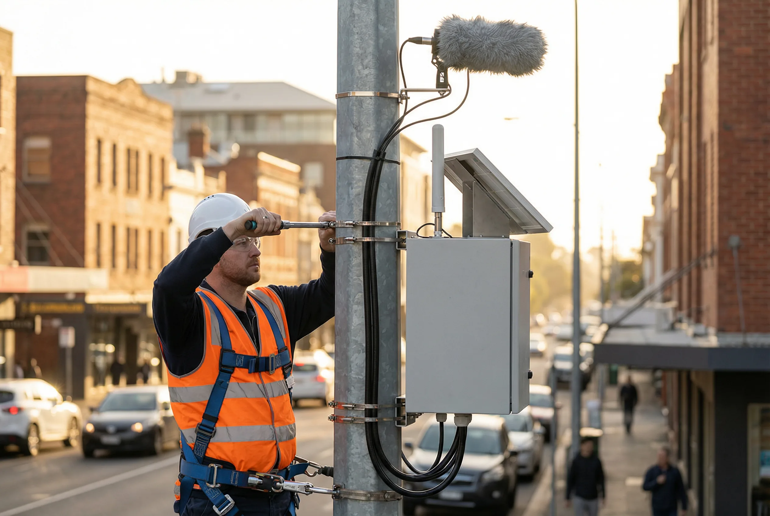
Figure 11.2: Professional ENMS installation in progress showing a certified technician using a torque wrench to secure stainless steel mounting clamps on a galvanized steel pole, with the weatherproof enclosure, solar panel, cellular antenna, and precision microphone with windscreen all correctly positioned and cables neatly routed through conduit
| Installation Parameter | Requirement | Standard Reference | Verification Method |
|---|---|---|---|
| Microphone height (general) | 1.2–4.0m above ground level | ISO 1996-2:2017 | Tape measure |
| Microphone height (road traffic) | 4.0m ± 0.2m AGL | EU END 2002/49/EC | Tape measure |
| Microphone height (facade) | 0.5m from facade, 1.5–4.0m AGL | ISO 1996-2:2017 | Laser distance meter |
| Microphone orientation | Free-field: 0° incidence; diffuse-field: 70–80° | IEC 61672-1 | Inclinometer |
| Minimum distance from reflector | ≥3.5× microphone height from any surface | ISO 1996-2:2017 | Tape measure |
| Pole vertical tolerance | ±2° from vertical | Manufacturer spec | Spirit level |
| Bolt torque (M8 SS) | 20–25 Nm | Manufacturer spec | Calibrated torque wrench |
| Cable bend radius (XLR) | ≥10× cable OD | Cable manufacturer | Visual inspection |
| Cable gland torque | Per manufacturer (typically 5–8 Nm) | Manufacturer spec | Torque wrench |
| Earth resistance | <10 Ω | IEC 62305 | Earth resistance tester |
Critical Warning — Microphone Orientation: The microphone must be oriented according to the instrument manufacturer's specification for the intended measurement geometry. Free-field microphones must face the dominant noise source at 0° incidence. Random-incidence (diffuse-field) microphones should be oriented at 70–80° to the dominant source. Incorrect orientation can introduce errors of 1–3 dB at high frequencies.
11.3 Commissioning Procedure
Commissioning is the systematic process of verifying that all system components are correctly installed, configured, and functioning before the system is placed into operational service. The commissioning procedure should be followed in the sequence listed below to ensure that each step is verified before proceeding to the next.
- Power system verification: Measure battery voltage (should be ≥12.6V for 12V LiFePO4), verify solar panel output under available light, confirm MPPT controller is operating in correct charge mode.
- Communication verification: Confirm cellular signal strength ≥-90 dBm, verify SIM card activation, test data transmission to platform with a test record, confirm receipt and correct parsing.
- GNSS time synchronization: Verify GNSS lock (≥4 satellites), confirm system time is synchronized to within 1 second of GPS time, verify PPS signal if used.
- Meteorological sensor verification: Compare wind speed and direction readings with a reference anemometer, verify temperature and humidity readings against a calibrated reference thermometer/hygrometer.
- Acoustic calibration check: Apply Class 1 pistonphone (114 dB, 1 kHz) to microphone, verify reading is within ±0.5 dB of reference, record calibration check result with timestamp.
- Functional test — measurement: Verify real-time LAeq, LCeq, and octave band measurements are updating at the correct interval, check that all required metrics are being calculated and stored.
- Alarm function test: Configure a test alarm threshold below the ambient level, verify that the alarm is triggered, transmitted to the platform, and acknowledged correctly.
- Data integrity verification: Retrieve the first 30 minutes of operational data from the platform, verify timestamps, data format, and completeness.
- Post-installation calibration check: Repeat acoustic calibration check after all cables are connected and the enclosure is sealed, to verify that installation has not affected the calibration.
- Documentation: Complete the commissioning checklist, photograph all installed components, record all configuration parameters, and file the commissioning report.
11.4 Common Installation Issues and Debugging
The table below presents the most common installation issues encountered during ENMS commissioning, their probable causes, and the recommended debugging procedures. Most issues can be resolved on-site with the tools and spare parts listed in Chapter 8.
| Issue | Symptoms | Probable Cause | Debugging Procedure |
|---|---|---|---|
| Calibration check fails (>±0.5 dB) | Pistonphone reading outside tolerance | Microphone contamination, cable fault, incorrect gain setting | Clean microphone, check XLR cable continuity, verify gain setting in software |
| No data on platform | Station appears offline | SIM not activated, incorrect APN, firewall blocking MQTT port | Check SIM status, verify APN settings, test port 8883 connectivity |
| Elevated noise floor | L90 higher than expected by 5+ dB | Vibration from pole/structure, electrical interference, wind noise | Check anti-vibration mounts, add cable ferrite, verify windscreen integrity |
| Battery not charging | Battery voltage declining despite sun | Solar panel shading, MPPT fault, battery BMS fault | Check panel output voltage, inspect MPPT controller LEDs, test battery OCV |
| GNSS no lock | Time synchronization failed | Antenna obstructed, antenna cable fault, interference | Check antenna sky view, test cable continuity, try alternative antenna location |
| Intermittent data gaps | Irregular missing records | Cellular coverage gaps, power brownouts, buffer overflow | Check signal strength log, monitor battery voltage, increase buffer size |
| Wind-induced noise spikes | High Lmax during windy periods | Windscreen damaged or missing, microphone exposed to direct wind | Replace windscreen, add secondary wind protection, reorient microphone |
| Incorrect frequency response | Octave band levels inconsistent with reference | Microphone type mismatch, incorrect preamplifier gain | Verify microphone model matches instrument configuration, check preamplifier settings |