Chapter 12: Operations & Maintenance
Preventive maintenance schedules, calibration management, remote monitoring, fault response procedures, and lifecycle management for ENMS networks
Environmental noise monitoring systems are long-term infrastructure investments that must deliver accurate, reliable data continuously over operational periods of 5–15 years or more. Achieving this performance requires a systematic operations and maintenance (O&M) program that combines remote monitoring, scheduled preventive maintenance, calibration management, and responsive fault resolution. This chapter provides a comprehensive O&M framework covering all aspects of ENMS lifecycle management, from daily remote monitoring through to end-of-life decommissioning and equipment replacement planning.
12.1 Field Calibration and Maintenance
Regular field calibration and maintenance visits are essential for maintaining measurement traceability and system reliability. The photograph below shows a certified technician performing a scheduled field calibration check using a Class 1 acoustic calibrator, with a complete field service kit containing all required tools and replacement parts.
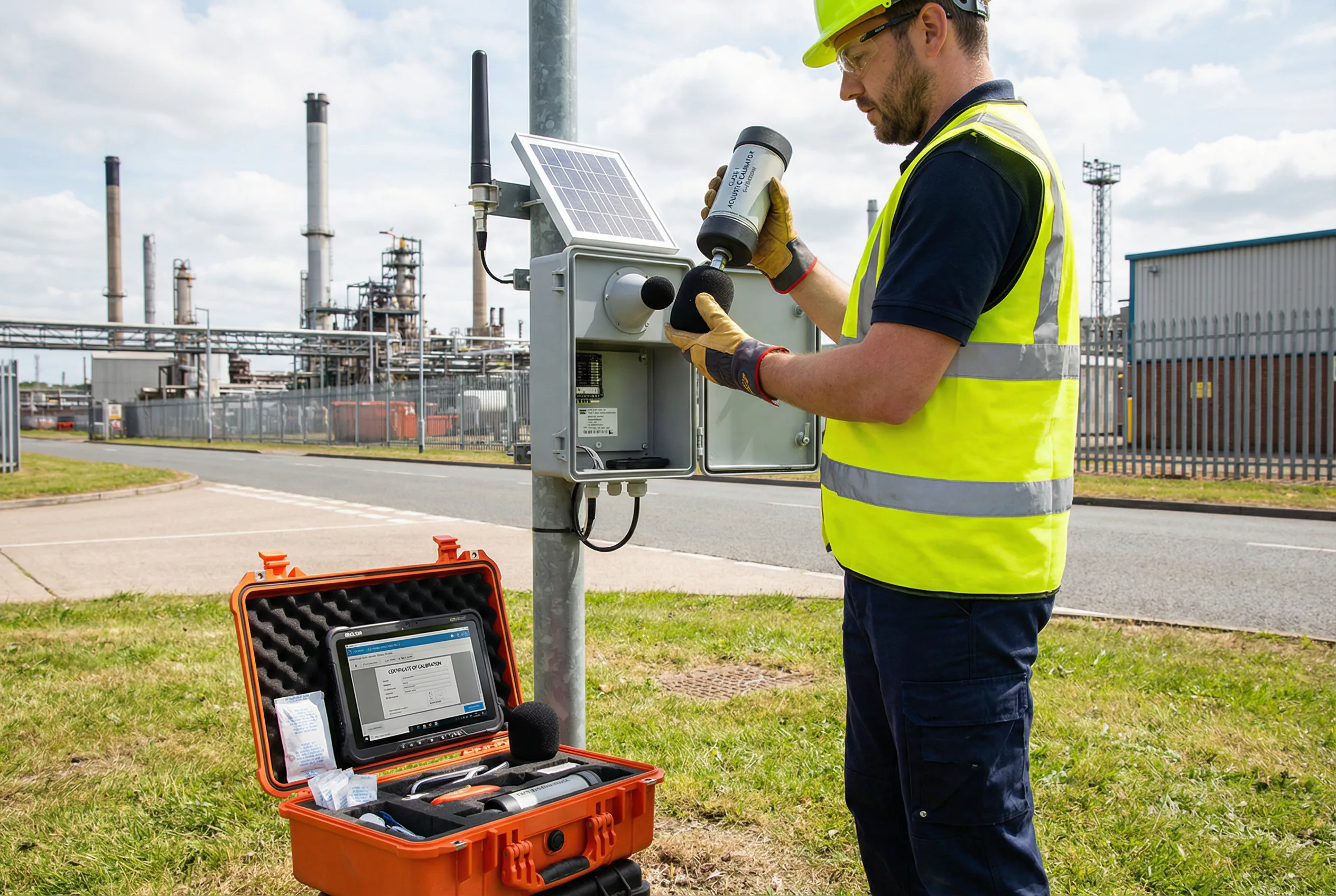
Figure 12.1: Certified acoustics technician performing scheduled field calibration using a Class 1 acoustic calibrator (pistonphone) on a noise monitoring station at an industrial boundary, with a complete field service kit containing calibration tools, spare windscreen, desiccant bags, and a tablet running calibration management software
Field calibration visits serve multiple purposes beyond the acoustic calibration check itself. The technician inspects the physical condition of all components, replaces consumables such as desiccant bags and windscreens, verifies the integrity of all cable connections and weatherproofing, cleans the solar panel and enclosure, and updates firmware if required. A comprehensive field visit report is completed and uploaded to the asset management system, creating a permanent maintenance record that supports regulatory audit and warranty claims.
12.2 Preventive Maintenance Schedule
The preventive maintenance schedule defines the frequency and scope of all planned maintenance activities. The schedule is designed to maintain system performance within specification, prevent unplanned failures, and ensure that calibration traceability is maintained throughout the operational period.
| Maintenance Task | Frequency | Duration | Skill Required | Tools/Materials |
|---|---|---|---|---|
| Remote system health check | Daily | 5 min (remote) | Operator | Platform dashboard |
| Data completeness review | Weekly | 15 min (remote) | Operator | Platform reports |
| Acoustic calibration check (field) | 6-monthly | 1 hour (on-site) | Acoustician | Class 1 calibrator, calibration form |
| Windscreen inspection and replacement | 6-monthly | 30 min (on-site) | Technician | Replacement windscreen |
| Desiccant bag replacement | 6-monthly | 15 min (on-site) | Technician | Desiccant bags |
| Solar panel cleaning | Quarterly | 30 min (on-site) | Technician | Soft cloth, deionized water |
| Battery capacity test | Annual | 2 hours (on-site) | Technician | Battery tester, multimeter |
| Full electrical inspection | Annual | 2 hours (on-site) | Electrician | Multimeter, torque wrench |
| Laboratory microphone calibration | Annual | 1 day (lab) | Metrologist | NATA/UKAS accredited lab |
| Firmware update | As released | 30 min (remote) | IT/Operator | Platform OTA update |
| Structural inspection (pole, clamps) | Annual | 1 hour (on-site) | Technician | Torque wrench, inspection form |
| Lightning protection test | Annual | 1 hour (on-site) | Electrician | Earth resistance tester |
| Full system recalibration | Every 2 years | Half day (on-site) | Acoustician | Reference SLM, calibrator, test signals |
12.3 Remote Monitoring and Alarm Management
Remote monitoring enables the O&M team to detect and respond to system issues without requiring a site visit. The platform should be configured with a comprehensive set of alarms covering acoustic exceedances, system health parameters, and communication failures. Effective alarm management requires clear escalation procedures, defined response time targets, and integration with the maintenance ticketing system.
| Alarm Type | Trigger Condition | Priority | Response Time Target | Initial Response Action |
|---|---|---|---|---|
| Noise exceedance | LAeq > regulatory limit | High | 15 minutes | Notify client; investigate source; log event |
| Station offline | No data received for >30 min | High | 30 minutes | Check cellular connectivity; remote restart; dispatch if needed |
| Calibration drift alarm | Auto-cal check deviation >0.5 dB | High | 4 hours | Flag data; schedule field calibration visit |
| Battery low | Battery SoC <20% | Medium | 4 hours | Check solar charging; adjust power management; plan visit |
| Communication degraded | Packet loss >10% or latency >5s | Medium | 4 hours | Check SIM status; test alternate network; escalate to carrier |
| Meteorological limit exceeded | Wind speed >10 m/s or temp out of range | Low | Next business day | Flag affected data; review met conditions; no action if transient |
| Firmware update available | New firmware version detected | Low | Next maintenance window | Review release notes; schedule update |
| Storage capacity warning | Local storage >80% full | Medium | 4 hours | Verify cloud sync; clear old data; increase storage if needed |
12.4 Lifecycle Management and Replacement Planning
ENMS components have different operational lifespans, and a proactive lifecycle management plan ensures that replacements are budgeted and procured before components reach end-of-life. The table below provides typical component lifespans and replacement triggers for planning purposes.
| Component | Typical Lifespan | Replacement Trigger | Replacement Cost (USD) | Planning Lead Time |
|---|---|---|---|---|
| Measurement microphone | 5–10 years | Sensitivity drift >1 dB; physical damage | $800–$3,000 | 4–8 weeks |
| Windscreen | 1–2 years | Visible damage; contamination; annual replacement | $50–$200 | 1–2 weeks |
| LiFePO4 battery | 5–8 years (2000+ cycles) | Capacity <80% of rated; BMS fault | $300–$800 | 4–6 weeks |
| Solar panel | 15–25 years | Output <80% of rated; physical damage | $150–$400 | 2–4 weeks |
| Cellular router | 5–8 years | Hardware fault; end-of-support; 5G upgrade | $300–$800 | 2–4 weeks |
| MPPT charge controller | 5–10 years | Charging fault; display failure | $100–$300 | 1–2 weeks |
| Weatherproof enclosure | 10–15 years | Seal failure; corrosion; physical damage | $200–$600 | 2–4 weeks |
| Mounting pole (galvanized) | 20–30 years | Corrosion; structural damage; wind damage | $300–$800 | 2–4 weeks |
| Core measurement unit | 8–12 years | Hardware fault; standard update; technology refresh | $3,000–$15,000 | 4–12 weeks |
| Surge protection devices | 5 years or after surge event | Status indicator shows fault; after lightning event | $50–$200 | 1 week |
Lifecycle Planning Recommendation: Develop a 10-year capital expenditure (CapEx) plan for your ENMS network at the time of initial deployment. Include replacement costs for all components with lifespans shorter than 10 years, calibration costs, and a 20% contingency for unplanned replacements. Review and update the plan annually. This approach prevents budget surprises and ensures that replacement procurement is initiated with sufficient lead time.
12.5 Key Performance Indicators for O&M
Key performance indicators (KPIs) provide a quantitative measure of O&M program effectiveness. The table below defines the recommended KPIs for ENMS O&M, with target values for standard and regulatory-grade deployments.
| KPI | Definition | Standard Target | Regulatory Grade Target | Measurement Frequency |
|---|---|---|---|---|
| System Availability | % of time system is operational and producing valid data | ≥95% | ≥98% | Monthly |
| Mean Time Between Failures (MTBF) | Average operating time between unplanned outages | ≥8,760 hours (1 year) | ≥17,520 hours (2 years) | Annual |
| Mean Time To Repair (MTTR) | Average time from fault detection to restoration | ≤24 hours | ≤4 hours | Monthly |
| Calibration Compliance Rate | % of calibrations completed on schedule | ≥95% | 100% | Quarterly |
| Calibration Pass Rate | % of calibration checks passed without adjustment | ≥90% | ≥95% | Per calibration visit |
| Preventive Maintenance Compliance | % of scheduled PM tasks completed on time | ≥90% | ≥98% | Monthly |
| Alarm Response Compliance | % of alarms responded to within target time | ≥90% | ≥98% | Monthly |
| Data Completeness | % of monitoring periods with complete, valid data | ≥90% | ≥98% | Monthly |