Chapter 2: Design Methods
Engineering principles, failure analysis, design decision logic, and key performance dimensions for ENMS deployment
2.1 Design Principles
Sound system design for environmental noise monitoring requires adherence to a set of engineering principles that balance measurement accuracy, operational resilience, long-term maintainability, and regulatory defensibility. These principles are derived from field experience across diverse deployment environments and are intended to guide decisions at every stage from site selection through acceptance testing and ongoing operations.
Evidence-First Design
Every design decision should be evaluated against the question: "Will this produce defensible evidence?" This means Class 1 instruments for enforcement, traceable calibration, immutable audit logs, and signed exports. Advisory deployments may relax some requirements, but the distinction must be explicit in the project specification.
Fail-Safe Buffering
Assume the uplink will fail. Every station must buffer locally for at least 7 days (30 days preferred for remote sites) and implement store-and-forward with exponential backoff. The platform must mark gaps as "pending backfill" rather than treating them as "no noise," and must verify backfill completeness after link restoration.
Separation of Concerns
The station computes stable, well-defined aggregates (LAeq, Lmax, percentiles, optional spectra). The platform performs heavy analytics, QA/QC, and reporting. Keeping the station simple and robust reduces field failures and simplifies firmware updates. Avoid pushing complex business logic to the station unless latency requirements demand it.
Explainability Over Black-Box
QA/QC rules, exceedance logic, and source correlation methods must be transparent, documented, and reproducible. Black-box AI models that cannot be explained to a regulator or court are not appropriate for enforcement-grade workflows. Every flag and alert must have a traceable rule reference.
Security Baseline Everywhere
Every internet-connected station is an attack surface. Unique device identity (certificates, not shared keys), TLS for all data transport, least-privilege access, signed OTA updates, and a defined vulnerability response process are non-negotiable baselines, not optional add-ons.
Lifecycle Cost (LCC) Optimization
Industrial-grade storage, proper surge protection, and robust enclosures cost more upfront but dramatically reduce truck rolls over a 5-10 year deployment. Design for the total cost of ownership, not just the initial BOM. Calibration scheduling, spare pool sizing, and remote diagnostics capability all directly affect LCC.
Interoperability by Default
Prefer standard protocols (MQTT/HTTPS/REST, NTP, SNMP), documented schemas with versioning, and modular integration adapters. Proprietary closed interfaces create vendor lock-in, increase integration costs, and make future upgrades expensive. Schema versioning prevents integration breakage during firmware updates.
2.2 Failure Causes & Recommendations
Understanding the most common failure patterns in deployed noise monitoring systems enables proactive design choices that prevent costly field problems. The table below summarizes eight critical failure patterns, their underlying mechanisms, engineering avoidance strategies, field symptoms, and verification methods. Each pattern has been observed in real deployments and represents a significant risk to data quality or system availability.
| Failure Pattern | Mechanism | Engineering Avoidance | Field Symptom | Verification |
|---|---|---|---|---|
| Frequent station resets | Power dip or surge transient | Add surge protection + proper PSU sizing + UPS where needed | Data gaps + reboot log entries | Power quality measurement, SPD inspection |
| Unrealistic noise spikes | Wind or rain impacting microphone | Better windscreen + mic placement review + QA flags for met correlation | Spikes correlating with windy or rainy hours | Compare with met data; wind flag audit |
| Long data gaps | Cellular CGNAT issues or weak RF coverage | High-gain antenna + VPN design + dual SIM failover | Offline alarms; missing intervals in dashboard | RSRP/SINR logs; VPN stability test |
| Wrong exceedance windows | Clock drift from NTP failure | GNSS or secured NTP + drift alarm threshold (≤5 s) | Alerts shifted in time vs. actual events | Drift audit report; time comparison |
| Corrupted history | Consumer SD card wear-out | Industrial SSD/SD with endurance rating + wear monitoring | Missing backfill after link restoration | Storage SMART/health monitoring |
| False "quiet" readings | Microphone failure (open circuit, moisture) | Mic fault detection (self-test + impedance check) + redundancy policy | Flatline noise levels; self-test fault code | Self-test routine; impedance measurement |
| Overheating shutdown | Solar load on sealed enclosure in summer | Thermal design with heat path analysis + sunshield + ventilation | Thermal alarms; elevated internal temperature trend | Temperature soak test; thermal trend review |
| Integration rejections | Schema mismatch after firmware update | Contract-first API design + schema versioning + integration tests | Failed export logs; regulator platform errors | Integration test suite; export validation |
2.3 Core Design & Selection Logic
The design selection process follows a structured decision sequence that begins with use case identification and ends with a complete configuration package. The decision tree below illustrates the three primary use case branches and the key decision points that determine station type, instrument class, communications redundancy, and optional components. Each branch leads to a specific configuration package tailored to the compliance and operational requirements of that scenario.
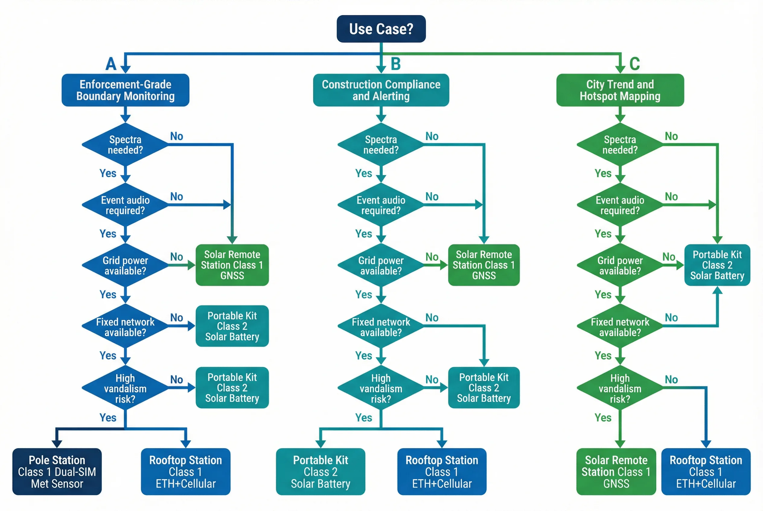
Figure 2.1: ENMS Design Decision Tree — Use Case Branches and Configuration Outcomes
Design Decision Sequence
- Identify scenario and compliance outcome — Is this enforcement-grade, advisory, or research? This determines instrument class and audit requirements.
- Determine required metrics — LAeq windows, Lmax, percentiles, SEL, and whether 1/3-octave spectra are needed for source characterization.
- Assess site environment class — Coastal corrosion, high dust, high vibration, EMI exposure, and vandalism risk all affect hardware selection.
- Make power decision — PoE (structured cabling), AC grid, or solar+battery. Solar requires autonomy calculation for worst-case irradiance.
- Make link decision — Ethernet primary, cellular primary, or dual-path. Dual SIM is recommended for enforcement-grade sites.
- Size the buffer — Minimum 7 days; 30 days for remote or high-stakes sites. Factor in worst-case link downtime from site history.
- Define QA/QC model — Met sensor integration, spectral anomaly checks, manual review workflow, and calibration interval.
- Define security model — VPN topology, device certificate issuance, role separation, and OTA signing.
- Define integration contract — Schema, payload frequency, retention period, and regulatory export format.
- Define O&M plan — Calibration cycles, spare pool, access control, and escalation SLA tiers.
2.4 Key Design Dimensions
A comprehensive ENMS design must be evaluated across seven key dimensions that span technical performance, operational resilience, and long-term cost. These dimensions provide a framework for comparing design alternatives and making informed trade-offs during the specification and procurement phases.
| Dimension | Key Considerations | Design Levers |
|---|---|---|
| Performance & User Experience | Alert latency, dashboard responsiveness, map usability, report generation time | Streaming rules engine, indexed time-series DB, CDN for GIS tiles |
| Stability & Reliability | Station availability, MTBF/MTTR, outage tolerance, backfill completeness | Industrial components, surge protection, dual-SIM, local buffer |
| Maintainability & Replaceability | Modular parts, field swap time, remote diagnostics coverage | Standardized connectors, remote reboot, OTA, spare pool |
| Compatibility & Scalability | Multi-vendor devices, schema versioning, horizontal ingestion scale | Standard protocols, versioned API, stateless ingestion services |
| Lifecycle Cost (LCC) | Truck rolls, calibration cost, storage/cloud cost, spare pool investment | Industrial storage, proactive replacement, remote diagnostics |
| Energy & Environmental | Low-power design, solar options, recyclable materials, thermal management | Low-power DSP, efficient PSU, solar sizing, sunshield |
| Compliance & Certification | Metrology standards, electrical safety, EMC, cybersecurity posture | Type-tested instruments, CE/IEC certifications, penetration testing |
Recommended Engineering Ranges
Aggregate interval: 1 min (core), 5 min/1 h (derived). Local buffer: 7–30 days. Uplink availability target: 99%–99.9%. Data completeness KPI: ≥99% monthly. Time drift alarm threshold: 2–5 s. Enclosure rating: IP65–IP66, IK08+. Surge protection: Type 2 (site) plus device-level SPD. Calibration interval: 6–12 months per policy.