Chapter 5: Selection & Interfaces
Core product selection criteria, interface specifications, typical wiring connections, and comprehensive feature comparison table
Selecting the appropriate hardware components for an environmental noise monitoring system requires a systematic evaluation of acoustic performance, environmental ratings, interface compatibility, power requirements, and total cost of ownership. This chapter presents the core product categories, their key selection parameters, the interface logic architecture, and a comprehensive feature comparison table to support procurement decisions.
5.1 Core Product Overview
A complete noise monitoring station comprises several distinct product categories, each with specific performance requirements that must be matched to the application scenario. The image below shows the primary hardware components of a standard monitoring station kit.
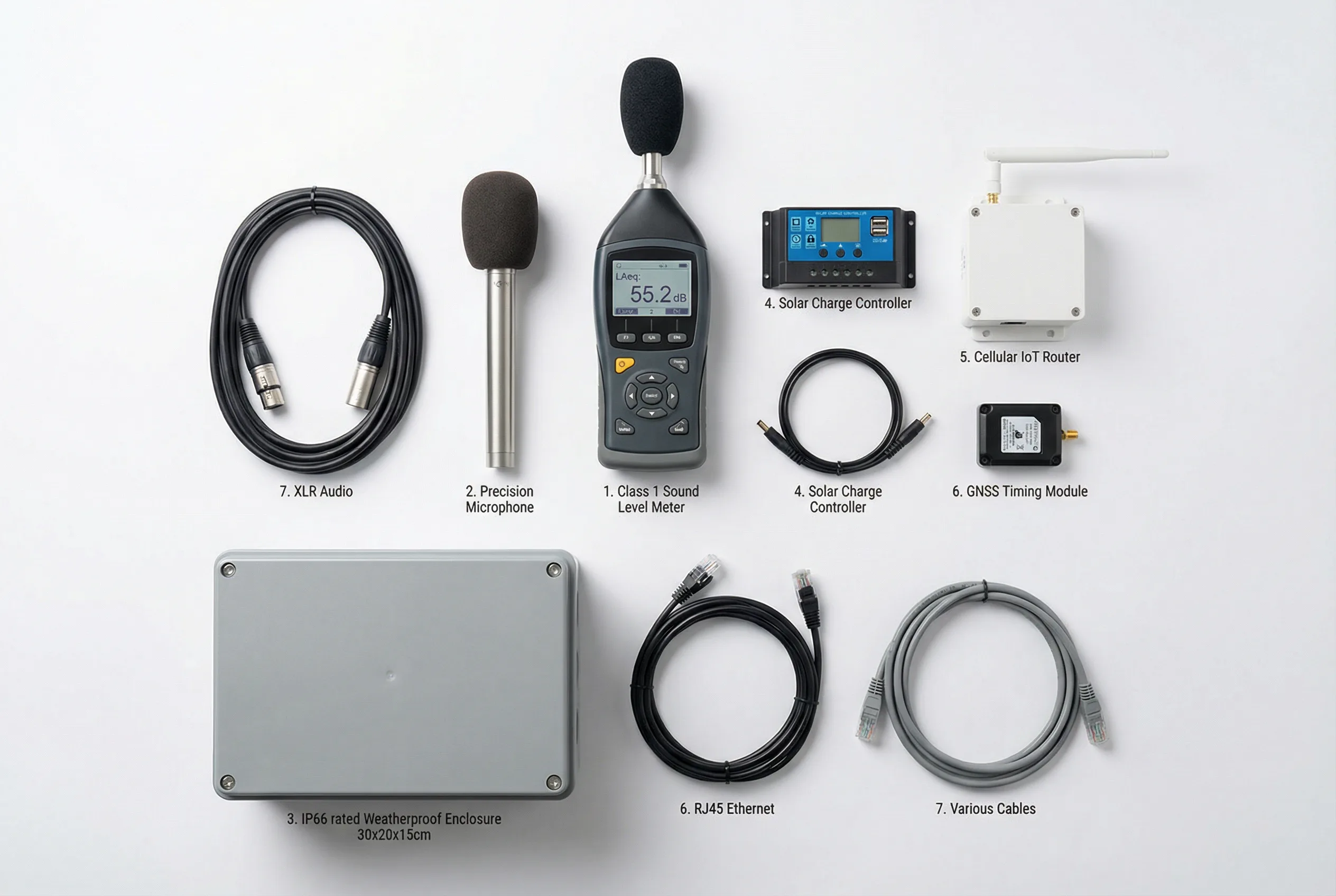
Figure 5.1: Core product components of a standard environmental noise monitoring station kit, including the Class 1 sound level meter, precision microphone, weatherproof enclosure, solar charge controller, cellular IoT router, GNSS timing module, and interconnecting cables
Class 1 Noise Monitor / Sound Level Meter
The primary measurement instrument. Must comply with IEC 61672-1 Class 1 for enforcement-grade applications. Key parameters: measurement range, self-noise, dynamic range, spectral analysis capability, and data logging capacity.
Precision Measurement Microphone
Free-field or pressure-field condenser microphone with windscreen. Frequency response 20 Hz–20 kHz ±1 dB. Self-noise <14 dB(A). Sensitivity −26 dBV/Pa typical. Must be matched to the instrument preamplifier.
Weatherproof Outdoor Enclosure
IP66 rated, IK08 minimum (IK10 for vandal-prone locations). Stainless steel or powder-coated aluminum. Integrated cable glands, DIN rail mounting, and ventilation with desiccant or active dehumidification.
Cellular IoT Router
Industrial-grade 4G/5G router with dual-SIM failover, VPN support, and serial-to-IP conversion. Operating temperature −40°C to +70°C. Watchdog timer for automatic recovery. MQTT/HTTPS protocol support.
Solar Charge Controller (MPPT)
Maximum Power Point Tracking controller for efficient solar energy harvesting. LiFePO4 battery profile support. Load output with low-voltage disconnect. Remote monitoring via RS-485 Modbus.
GNSS Timing Module
Multi-constellation GNSS receiver (GPS/GLONASS/BeiDou/Galileo) providing ±1 ms time synchronization. PPS output for precise timestamp alignment. USB or UART interface. Required for airport and rail applications.
5.2 Interface Logic Architecture
The interface logic diagram illustrates the complete input and output interface structure of the noise monitor controller, showing how all peripheral devices connect to the central processing unit. Understanding this architecture is essential for system integration and troubleshooting.
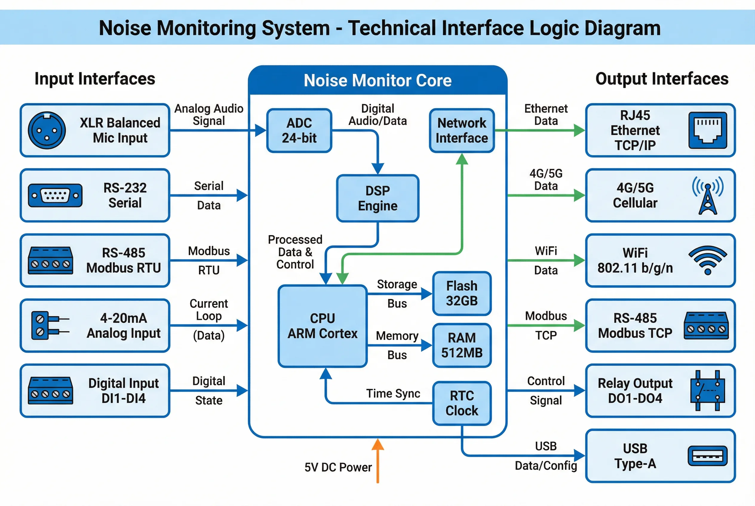
Figure 5.2: Noise monitor controller interface logic diagram showing all input interfaces (microphone, serial, Modbus, analog, digital), core processing components (ADC, DSP, CPU, memory, RTC), and output interfaces (Ethernet, cellular, WiFi, Modbus TCP, relay, USB)
The interface architecture separates acoustic signal processing from data communication. The 24-bit ADC converts the analog microphone signal to digital with sufficient resolution to capture the full dynamic range of the instrument. The DSP Engine performs real-time computation of acoustic metrics including LAeq, Lmax, Lmin, L10, L50, L90, 1/3-octave spectra, and SEL. The ARM Cortex CPU manages data storage, communication protocols, QA/QC logic, and the user interface. The RTC (Real-Time Clock) maintains time synchronization, optionally disciplined by a GNSS PPS signal for sub-millisecond accuracy.
5.3 Core Product Feature Comparison Table
The table below provides a comprehensive comparison of the key features and specifications across the four main product tiers commonly available in the market. This comparison enables informed selection based on application requirements and budget constraints.
| Feature / Specification | Entry Level (Class 2) | Standard (Class 1) | Professional (Class 1+) | Reference Grade |
|---|---|---|---|---|
| IEC 61672 Class | Class 2 | Class 1 | Class 1 | Class 1 (traceable) |
| Measurement Range | 35–130 dB(A) | 30–140 dB(A) | 20–140 dB(A) | 15–140 dB(A) |
| Microphone Self-Noise | <25 dB(A) | <16 dB(A) | <14 dB(A) | <10 dB(A) |
| Frequency Analysis | A, C, Z weighting | 1/1-octave | 1/3-octave | 1/3-octave + FFT |
| Sampling Rate | 48 kHz | 48 kHz | 96 kHz | 192 kHz |
| ADC Resolution | 16-bit | 24-bit | 24-bit | 32-bit |
| Metrics Computed | LAeq, Lmax, Lmin | LAeq, Lmax, Lmin, L10/L90, SEL | All + Lden, Lnight, EPNL | All + custom metrics |
| Local Storage | 8 GB | 32 GB | 64 GB | 256 GB SSD |
| Data Retention (local) | 7 days (1-min data) | 30 days | 90 days | 365 days |
| Connectivity | 4G LTE single SIM | 4G LTE dual SIM | 4G/5G dual SIM + Ethernet | 5G + Fiber + Satellite |
| GNSS Time Sync | ✗ | Optional | ✓ Standard | ✓ ±1 ms PPS |
| Met Sensor Interface | RS-485 (1 sensor) | RS-485 Modbus (4 sensors) | RS-485 + 4-20mA (8 sensors) | All protocols (16 sensors) |
| Audio Recording | ✗ | Optional WAV | ✓ Event-triggered WAV | ✓ Continuous + event |
| Relay Outputs | 1 relay | 2 relays | 4 relays | 8 relays + 4-20mA out |
| Operating Temperature | −20°C to +55°C | −30°C to +60°C | −40°C to +65°C | −40°C to +70°C |
| Enclosure Rating | IP54 | IP65 | IP66 | IP67, IK10 |
| Calibration Interval | Annual | 6 months | 6 months | Annual (NATA/UKAS) |
| Typical Unit Price (USD) | $2,000–$5,000 | $5,000–$12,000 | $12,000–$25,000 | $25,000–$60,000 |
| Typical Application | Community surveys, screening | Compliance monitoring, enforcement | Airport, rail, industrial | National reference networks |
5.4 Microphone Selection Criteria
The measurement microphone is the most acoustically critical component of the system. Its selection must be carefully matched to the measurement environment, the required frequency range, and the expected sound pressure levels. The table below summarizes the key microphone types and their application suitability.
| Microphone Type | Capsule Size | Self-Noise | Max SPL | Best Application |
|---|---|---|---|---|
| 1/2" Free-Field (standard) | 12.7 mm | 14–18 dB(A) | 140 dB | General environmental monitoring |
| 1/2" Low-Noise | 12.7 mm | 8–12 dB(A) | 135 dB | Nature reserves, background noise surveys |
| 1/4" Free-Field | 6.35 mm | 22–26 dB(A) | 160 dB | High-SPL industrial, aircraft |
| 1" Free-Field | 25.4 mm | 4–8 dB(A) | 130 dB | Ultra-low noise reference measurements |
| MEMS Digital | Varies | 28–35 dB(A) | 120 dB | Low-cost IoT screening nodes |
5.5 Selection Decision Matrix
The decision matrix below provides a structured approach to hardware selection based on the primary application requirements. Each cell indicates the recommended product tier for the intersection of application type and performance requirement.
| Application | Regulatory Requirement | Recommended Class | Connectivity | Power | Special Features |
|---|---|---|---|---|---|
| Urban Traffic | National standard | Class 1 Standard | Dual-SIM 4G | Grid + Solar | Vibration isolation |
| Construction | Permit condition | Class 1 Standard | 4G + WiFi | Solar + Battery | Real-time alert, portable |
| Industrial | Environmental permit | Class 1 Professional | Fiber + 4G | Grid + UPS | 1/3-octave, met sensor |
| Airport | ICAO / FAA | Class 1 Professional | Fiber + 4G | Grid | GNSS, flight correlation |
| Rail/Metro | TSI Noise / EN 3095 | Class 1 Professional | Ethernet + 4G | Grid / PoE | Vibration isolation, EMI |
| School/Hospital | WHO guidelines | Class 1 Standard | WiFi / 4G | Solar / PoE | Low-noise mic, no audio |
| Entertainment | Local ordinance | Class 1 or 2 | Dual-SIM 4G | Grid AC | IK10, complaint API |
| Remote/Nature | Research / permit | Class 1 Professional | Satellite | Solar + Wind | Ultra-low noise, GNSS |