Chapter 7: Support & Integration
Supporting equipment requirements, third-party system integration, API specifications, and interoperability standards for ENMS deployments
A complete environmental noise monitoring system extends well beyond the core measurement instrument to encompass a comprehensive ecosystem of supporting equipment, integration interfaces, and third-party system connections. Supporting equipment provides the power, communication, environmental protection, timing, and physical mounting infrastructure that enables the core instrument to operate reliably in unattended outdoor environments. Integration interfaces connect the ENMS to regulatory authority platforms, GIS systems, public information portals, and operational management tools. This chapter describes the full supporting equipment ecosystem and the integration architecture that connects ENMS data to downstream systems.
7.1 Integrated Supporting Equipment Overview
The infographic below presents all nine categories of supporting equipment required for a complete ENMS deployment in a single integrated view. Each category serves a specific functional role in the overall system, and the selection of specific products within each category must be coordinated to ensure compatibility and optimal performance.
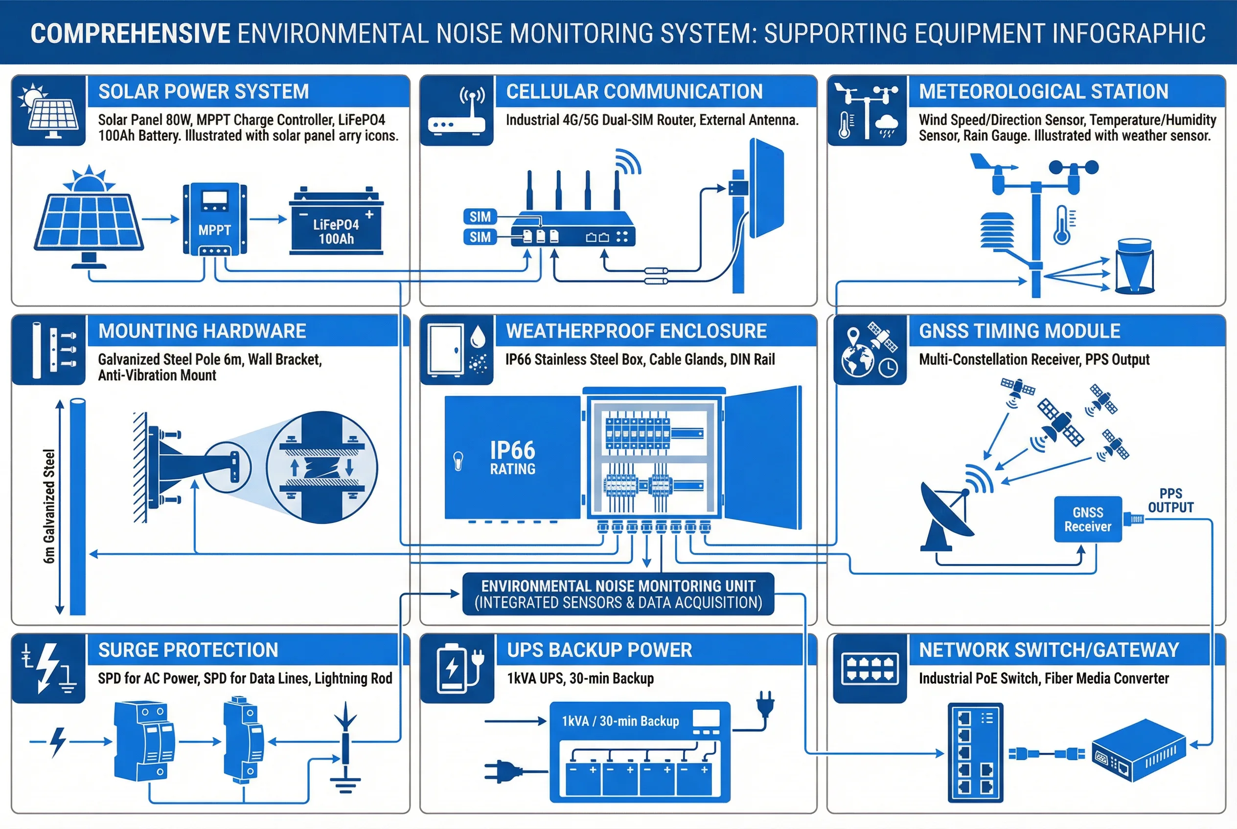
Figure 7.1: Comprehensive supporting equipment infographic showing all nine categories integrated in a single view: Solar Power System, Cellular Communication, Meteorological Station, Mounting Hardware, Weatherproof Enclosure, GNSS Timing Module, Surge Protection, UPS Backup Power, and Network Switch/Gateway
The nine supporting equipment categories shown in the infographic work together as an integrated system. The Solar Power System harvests energy from photovoltaic panels and stores it in a LiFePO4 battery bank via an MPPT charge controller, providing reliable off-grid power. The Cellular Communication module transmits data from the field station to the cloud platform via dual-SIM 4G/5G connectivity with automatic failover. The Meteorological Station provides wind speed, wind direction, temperature, humidity, and barometric pressure data that enables meteorological correction of acoustic measurements and flagging of data collected under adverse conditions. The Mounting Hardware secures all components safely and provides vibration isolation to prevent structure-borne noise from contaminating measurements. The Weatherproof Enclosure protects all electronics from rain, dust, humidity, and temperature extremes. The GNSS Timing Module provides precise time synchronization for accurate data timestamping and event correlation. The Surge Protection system guards against lightning-induced transients on power and communication cables. The UPS Backup Power provides bridge power during grid outages for grid-connected stations. The Network Switch/Gateway aggregates data from multiple sensors and provides protocol translation.
7.2 Supporting Equipment Specifications
The table below provides the key technical specifications for each supporting equipment category, enabling procurement teams to identify suitable products and verify compatibility with the core monitoring system.
| Equipment Category | Key Specifications | Interface to Core System | Typical Brands |
|---|---|---|---|
| Solar Panel | 80–200W monocrystalline, 12/24V, IP65, -40°C to +85°C | DC cable to MPPT controller | Jinko, LONGi, Canadian Solar |
| MPPT Charge Controller | 20–40A, LiFePO4 profile, RS-485 Modbus, LCD display | RS-485 Modbus to core system | Victron, Epever, Renogy |
| LiFePO4 Battery | 50–200Ah, 12.8V or 25.6V, BMS, -20°C to +60°C, cycle life >2000 | DC power to system | CATL, Winston, Lithium Werks |
| 4G/5G Cellular Router | Dual-SIM, CAT12+, VPN, -40°C to +70°C, DIN rail mount | Ethernet RJ45 to core system | Sierra Wireless, Teltonika, Robustel |
| Meteorological Station | Wind 0–60 m/s, Temp -40°C to +80°C, RH 0–100%, RS-485 | RS-485 Modbus RTU to core | Vaisala, Campbell Scientific, Davis |
| Mounting Pole | Galvanized steel, 4–8m, 60–76mm OD, wind load rated ≥150 km/h | Physical mounting only | Local fabrication or Unistrut |
| Weatherproof Enclosure | IP66, IK10, stainless or powder-coated aluminum, DIN rail, 300×400×200mm | Physical housing | Rittal, Fibox, Spelsberg |
| GNSS Module | GPS/GLONASS/BeiDou, ±1 ms PPS, USB or UART, -40°C to +85°C | USB or UART to core system | u-blox, Trimble, NovAtel |
| Surge Protection Device | AC SPD Type 2, 40kA; RS-485 SPD 5V; Ethernet SPD Cat6 | In-line on all cables | Phoenix Contact, Citel, Dehn |
| UPS (for grid stations) | 500W–2kVA, online double-conversion, 30–60 min autonomy, RS-232 | RS-232 to core for status | APC, Eaton, CyberPower |
| Industrial PoE Switch | 8-port, PoE+ 802.3at, -40°C to +75°C, DIN rail, managed | Ethernet to core and sensors | Cisco IE, Moxa, Advantech |
7.3 Third-Party System Integration
ENMS platforms must integrate with a range of external systems to fulfill their regulatory reporting, public information, and operational management functions. Integration design must address data format compatibility, authentication, rate limiting, and error handling for each external connection.
| External System | Integration Type | Protocol / Format | Data Direction | Key Considerations |
|---|---|---|---|---|
| Regulatory Authority Platform | Automated reporting | REST API, XML (HJ 212), CSV | ENMS → Regulator | Submission frequency, data format standard, authentication token |
| GIS / Mapping System | Spatial data export | GeoJSON, WMS/WFS, KML | Bidirectional | Coordinate system (WGS84), update frequency, layer management |
| Complaint Management System | Event correlation | REST API, webhook | Bidirectional | Complaint timestamp matching, station proximity query |
| Public Information Portal | Real-time display | REST API, WebSocket | ENMS → Portal | Data latency ≤5 min, display format, privacy filtering |
| SCADA / BMS | Alarm integration | Modbus TCP, OPC-UA, MQTT | ENMS → SCADA | Alarm mapping, acknowledgment protocol, failsafe behavior |
| Weather Service API | Meteorological data | REST API, JSON | Weather → ENMS | Forecast data for predictive alerts, backup to local met station |
| Asset Management System | Equipment lifecycle | REST API, CSV | Bidirectional | Calibration due dates, maintenance history, spare parts inventory |
| Ticketing / Helpdesk | Fault management | REST API (Jira, ServiceNow) | ENMS → Ticketing | Auto-ticket on alarm, SLA tracking, resolution workflow |
API Design Best Practice: All ENMS platform APIs should follow RESTful design principles with OpenAPI 3.0 documentation. Authentication should use OAuth 2.0 with short-lived access tokens. Rate limiting should be implemented to prevent accidental or deliberate overload. All API endpoints should support pagination for large data queries and include standard HTTP status codes with descriptive error messages.
7.4 Communication Protocol Stack
The protocol stack defines the communication standards used at each layer of the ENMS architecture, from the physical sensor interface to the regulatory reporting endpoint. Adherence to standard protocols ensures interoperability and simplifies integration with third-party systems.
| Layer | Protocol | Application | Standard Reference |
|---|---|---|---|
| Sensor to Controller | RS-485 Modbus RTU | Meteorological sensors, calibrators | Modbus Application Protocol v1.1b |
| Controller to Router | Ethernet TCP/IP | Data uplink, configuration | IEEE 802.3 |
| Station to Platform | MQTT over TLS 1.3 | Real-time data streaming | MQTT v5.0, RFC 8446 |
| Station to Platform | HTTPS REST | Batch data upload, configuration | RFC 7231, OpenAPI 3.0 |
| Platform to Regulator | HTTPS + HJ 212 | Regulatory data submission | HJ 212-2017 (China), local equivalent |
| Platform to GIS | OGC WFS/WMS | Spatial data services | OGC WFS 2.0, WMS 1.3 |
| Time Synchronization | NTP / PTP | System clock synchronization | RFC 5905 (NTP), IEEE 1588 (PTP) |
| Device Management | TR-069 / LwM2M | Remote configuration, firmware update | Broadband Forum TR-069, OMA LwM2M |